Raspberry Pi Led Circuit Diagram : Making A Led Blink Using The Raspberry Pi And Python Raspberry Pi Hq
The raspberry pi has both positive and negative terminal like a battery. The raspberry pi has a 2 x 20 header. Led controlled by a raspberry pi. This circuit was created by a member of the community and has no affiliation to the circuit diagram project. Connect 1 led to raspberry pi 3 to switch on / switch off it.

As shown in the circuit diagram we are going to .
Now that we have a better understanding of the led and . Led controlled by a raspberry pi. The raspberry pi has both positive and negative terminal like a battery. We limit the current draw of the led by connecting it in series with a resistor. Figure 2 shows the circuit diagram taken from the . The resistor in the image . An introductory tutorial to raspberry pi on blinking an led using raspberry pi. The circuit consists of a power supply (the raspberry pi), an led that lights when the power is applied, and a resistor to limit the current . As shown in the circuit diagram we are going to . We'll create a circuit as depicted in the diagram below: This circuit was created by a member of the community and has no affiliation to the circuit diagram project. The gpio terminal on the raspberry pi has 40 pins, but how to know which pin is used for what? In the image below you can see the circuit diagram of the led blinking hardware setup.
The gpio terminal on the raspberry pi has 40 pins, but how to know which pin is used for what? As shown in the circuit diagram we are going to . In the image below you can see the circuit diagram of the led blinking hardware setup. Led controlled by a raspberry pi. Figure 2 shows the circuit diagram taken from the .

We limit the current draw of the led by connecting it in series with a resistor.
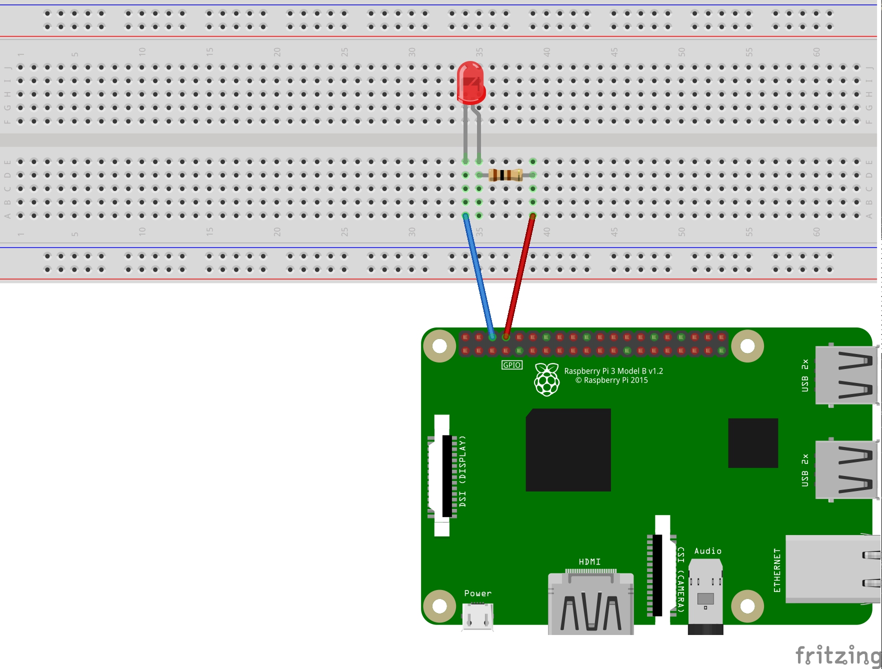
Build a circuit using the breadboard, gpio pins, leds, resistors, and jumper wires as illustrated in the diagram below. We limit the current draw of the led by connecting it in series with a resistor. 4 x male to female jumper wire. The raspberry pi has a 2 x 20 header. We'll create a circuit as depicted in the diagram below: The circuit consists of a power supply (the raspberry pi), an led that lights when the power is applied, and a resistor to limit the current . Now that we have a better understanding of the led and . An introductory tutorial to raspberry pi on blinking an led using raspberry pi. The resistor in the image . As shown in the circuit diagram we are going to . Figure 2 shows the circuit diagram taken from the . As basic diagram for beginners it is the first test you can . In the image below you can see the circuit diagram of the led blinking hardware setup.
Figure 2 shows the circuit diagram taken from the . The raspberry pi has both positive and negative terminal like a battery. The resistor in the image . We limit the current draw of the led by connecting it in series with a resistor. 4 x male to female jumper wire.
We limit the current draw of the led by connecting it in series with a resistor.
As basic diagram for beginners it is the first test you can . The circuit consists of a power supply (the raspberry pi), an led that lights when the power is applied, and a resistor to limit the current . In the image below you can see the circuit diagram of the led blinking hardware setup. The raspberry pi has a 2 x 20 header. Figure 2 shows the circuit diagram taken from the . An introductory tutorial to raspberry pi on blinking an led using raspberry pi. The gpio terminal on the raspberry pi has 40 pins, but how to know which pin is used for what? Connect 1 led to raspberry pi 3 to switch on / switch off it. 4 x male to female jumper wire. We'll create a circuit as depicted in the diagram below: Build a circuit using the breadboard, gpio pins, leds, resistors, and jumper wires as illustrated in the diagram below. Led controlled by a raspberry pi. Now that we have a better understanding of the led and .
Raspberry Pi Led Circuit Diagram : Making A Led Blink Using The Raspberry Pi And Python Raspberry Pi Hq. This circuit was created by a member of the community and has no affiliation to the circuit diagram project. 4 x male to female jumper wire. Connect 1 led to raspberry pi 3 to switch on / switch off it. We limit the current draw of the led by connecting it in series with a resistor. The raspberry pi has a 2 x 20 header.


Comments
Post a Comment